Product
ISBM
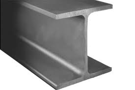
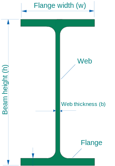
Indian Standard Medium weight Beams abbreviated as ISMB are widely used today in construction and civil engineering field. The horizontal section of the “I” is termed as Flanges and the vertical section is termed as Web. Both of these play an important role. While the web resists shear forces, the flange plays in important role is resisting bending moment.
- I Beams today are either Rolled(hot rolling, cold rolling or extrusion) or formed by welding plates.
- I-beams are widely used in the construction industry and are available in a variety of standard sizes. I-beams may be used both as beams and as columns.
- I-beams may be used both on their own, or acting compositely with another material, typically concrete. Design may be governed by any of the following criteria:
- deflection: the stiffness of the I-beam will be chosen to minimize deformation
- vibration: the stiffness and mass are chosen to prevent unacceptable vibrations, particularly in settings sensitive to vibrations, such as offices and libraries
- bending failure by yielding: where the stress in the cross section exceeds the yield stress
- bending failure by lateral torsional buckling: where a flange in compression tends to buckle sideways or the entire cross-section buckles torsionally
- bending failure by local buckling: where the flange or web is so slender as to buckle locally
- local yield: caused by concentrated loads, such as at the beam’s point of support
- shear failure: where the web fails. Slender webs will fail by buckling, rippling in a phenomenon termed tension field action, but shear failure is also resisted by the stiffness of the flanges
- buckling or yielding of components: for example, of stiffeners used to provide stability to the I-beam’s web.

A beam under bending sees high stresses along the axial fibers that are farthest from the neutral axis. To prevent failure, most of the material in the beam must be located in these regions. Comparatively little material is needed in the area close to the neutral axis. This observation is the basis of the I-beam cross-section; the neutral axis runs along the centre of the web which can be relatively thin and most of the material can be concentrated in the flanges.
The ideal beam is the one with the least cross-sectional area (and hence requiring the least material) needed to achieve a given section modulus. Since the section modulus depends on the value of the moment of inertia, an efficient beam must have most of its material located as far from the neutral axis as possible. The farther a given amount of material is from the neutral axis, the larger is the section modulus and hence a larger bending moment can be resisted.
When designing a symmetric I-beam to resist stresses due to bending the usual starting point is the required section modulus. If the allowable stress is![]() and the maximum expected bending moment is
and the maximum expected bending moment is ![]() , then the required section modulus is given by [3]
, then the required section modulus is given by [3]

However, these ideal conditions can never be achieved because material is needed in the web for physical reasons, including to resist buckling. For wide-flange beams, the section modulus is approximately
which is superior to that achieved by rectangular beams and circular beams.
Though I-beams are excellent for unidirectional bending in a plane parallel to the web, they do not perform as well in bidirectional bending. These beams also show little resistance to twisting and undergo sectional warping under torsional loading. For torsion dominated problems, box beams and other types of stiff sections are used in preference to the I-beam.
|
Size |
Web Size in mm |
Flange Size in mm |
Weight per mtr |
|
100×75 |
100 |
75 |
11.5 |
|
100×50 |
100 |
50 |
8.5 |
|
125×75 |
125 |
75 |
13 |
|
150×80 |
150 |
80 |
14.9 |
|
175×90 |
175 |
90 |
19.3 |
|
200×100 |
200 |
100 |
25.4 |
|
250×125 |
250 |
125 |
37.3 |
|
300×140 |
300 |
140 |
44.2 |
|
350×140 |
350 |
140 |
52.4 |
|
400×140 |
400 |
140 |
61.6 |
|
450×150 |
450 |
150 |
72.4 |
|
500×180 |
500 |
180 |
86.9 |
|
600×250 |
600 |
250 |
122.6 |


